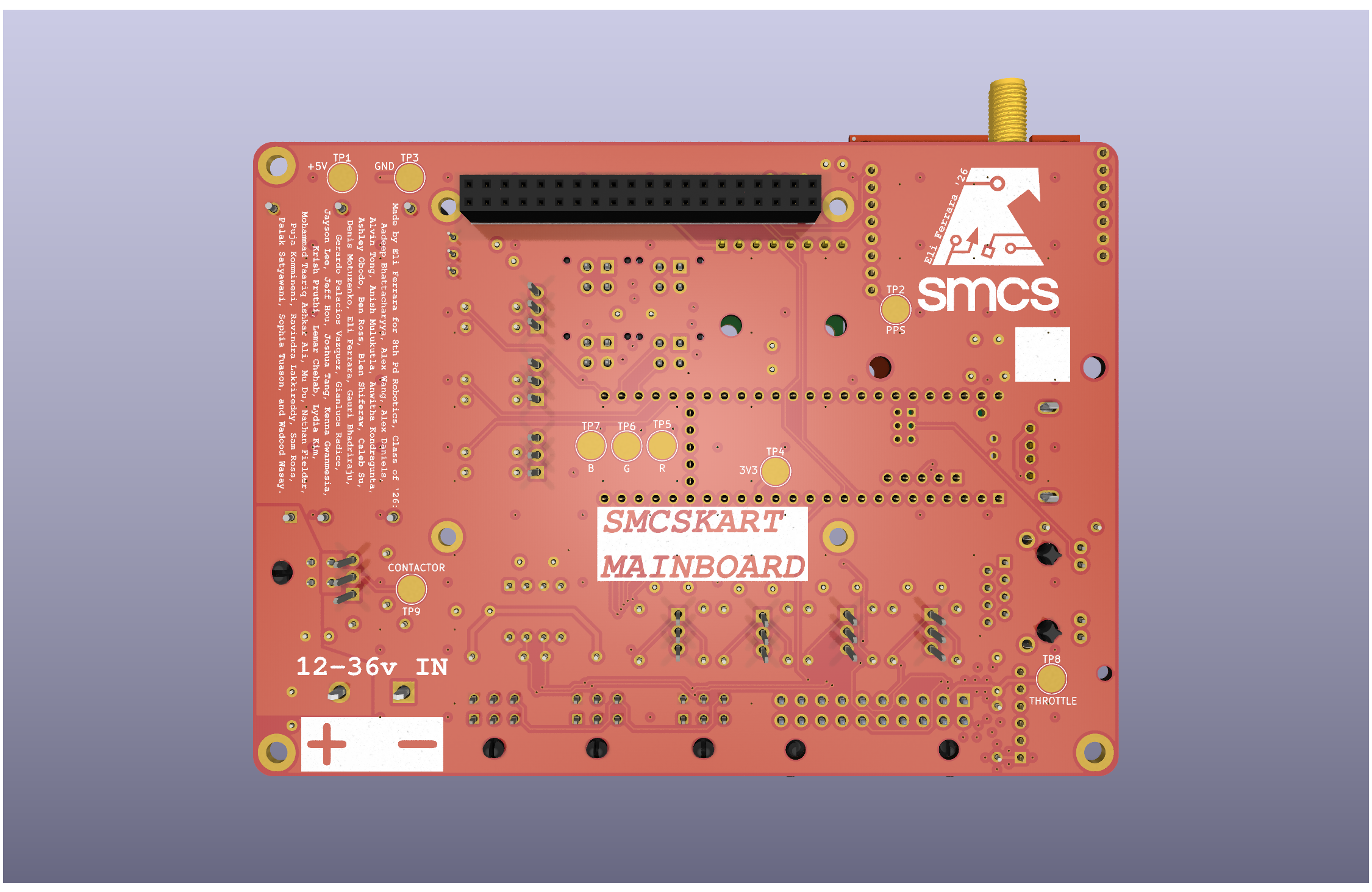
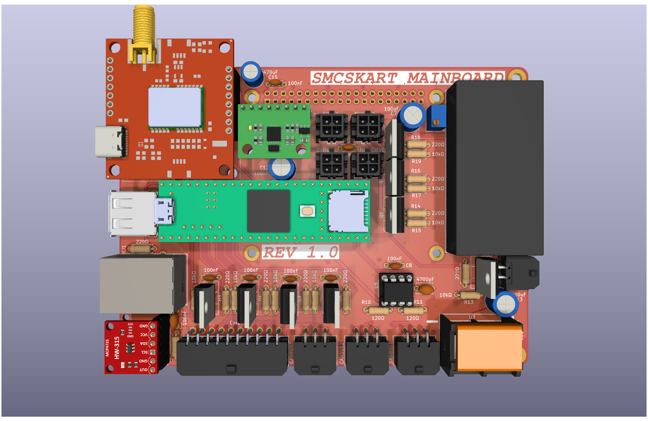
SMCSKart Mainboard
Mirror for software reference. This doc is copied here so firmware/Pi work
has the pin map without checking out the hardware repo. The canonical
source for the board is PHS-SMCS/SMCSKart-Mainboard (its KiCad schematic);
if a pin assignment here ever disagrees with the board, the board wins — update
this mirror to match.
Custom PCB integrating every system in the SMCS Robotics 8th period go-kart. The board acts as the central hub between a Raspberry Pi 4, a Teensy 4.1, all motor controller I/O, sensors, and peripherals.
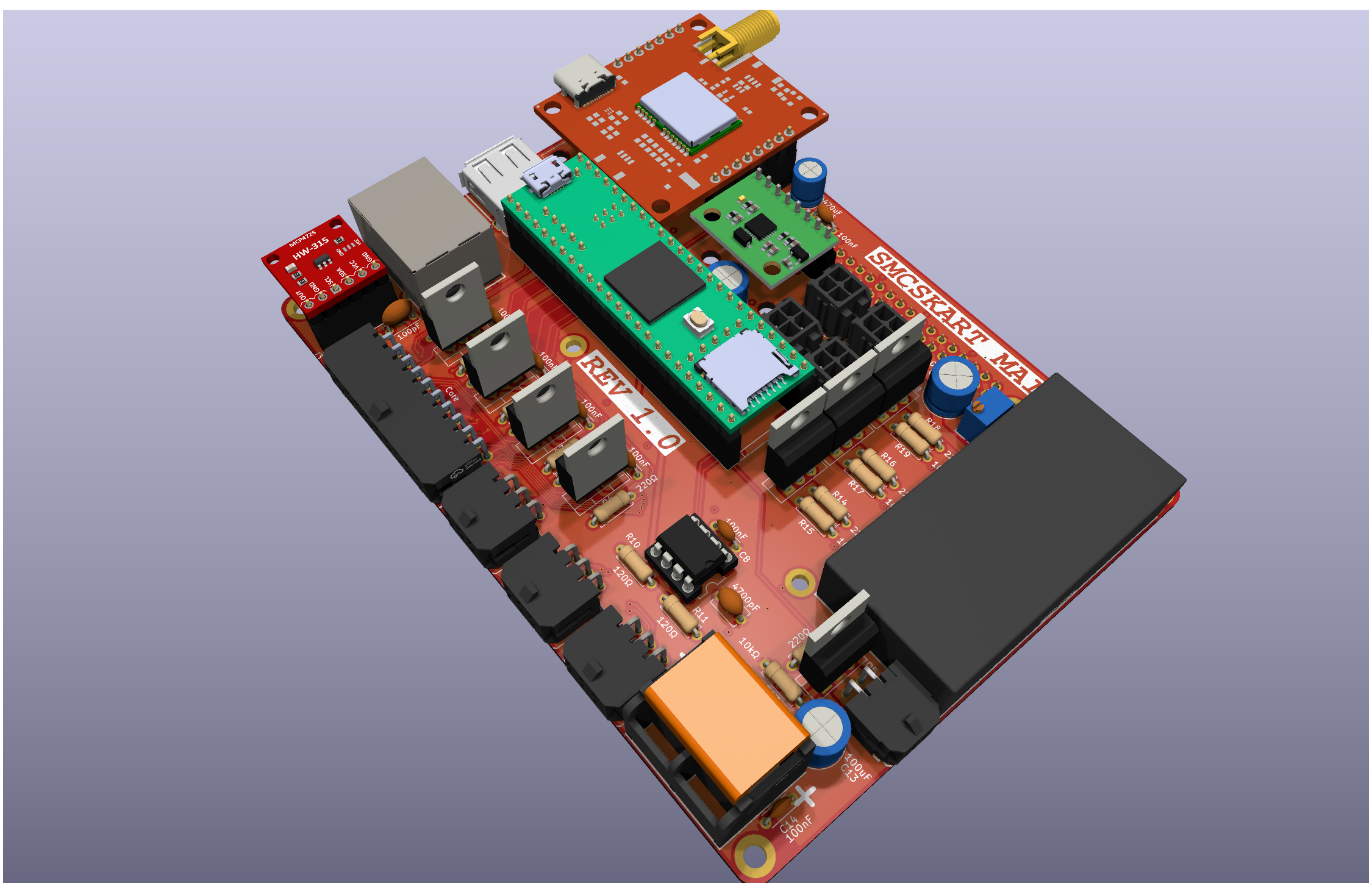
Components
| Component |
Description |
| Raspberry Pi 4 |
Main compute; connected via 40-pin header |
| Teensy 4.1 |
Real-time microcontroller with onboard Ethernet |
| NEO-M9N |
GPS module (connected to Pi I2C + PPS to Teensy) |
| MPU6050 |
6-axis accelerometer/gyroscope (connected to Pi I2C) |
| MCP4725 |
12-bit DAC for throttle signal generation (connected to Teensy I2C) |
| MCP2562-E/P |
CAN bus transceiver |
| IRLZ44N |
Logic-level N-channel MOSFETs for all toggle/switch outputs (with pulldown resistors) |
| ND721000 |
FarDriver BLDC/PMSM speed controller (RS232 interface) |
Power Rails
The board supplies three voltage rails available on the extra power port:
| Rail |
Voltage |
| 3V3 |
3.3 V |
| 5V |
5 V |
| 24V |
24 V (also used for LED strip) |
Teensy 4.1 Pin Assignments
Serial / UART
| Pin(s) |
Interface |
Connected To |
Notes |
| 0, 1 |
Serial1 (TX, RX) |
ND721000 ESC |
RS232 level — programming/telemetry port on ESC |
| 7, 8 |
Serial2 (TX, RX) |
Raspberry Pi 4 |
UART bridge between Teensy and Pi |
| 14, 15 |
Serial3 (TX, RX) |
Transceiver module |
RF/wireless transceiver comms |
| 34, 35 |
Serial8 (TX, RX) |
FPV camera |
UART control for FPV camera |
I2C
| Pin(s) |
Bus |
Connected To |
| 18, 19 |
SDA, SCL |
MCP4725 DAC (throttle control) |
CAN Bus
| Pin(s) |
Signal |
Notes |
| 30, 31 |
CRX, CTX |
Via MCP2562-E/P transceiver; 120 Ω termination required at each end |
Digital I/O — ESC Control & Sensors
All toggle output pins drive an IRLZ44N MOSFET with a pulldown resistor, providing an active-low ground signal to the ESC connector.
| Pin |
Function |
ESC Signal |
Direction |
| 2 |
Hall Pulses input |
Hall Pulses (ESC pin 18) |
Input from ESC |
| 3 |
Reverse toggle |
REV (ESC pin 8) |
Output to ESC |
| 4 |
Brake toggle |
Low Brake (ESC pin 21) |
Output to ESC |
| 5 |
High speed toggle |
High Speed (ESC pin 3) |
Output to ESC |
| 6 |
Low speed toggle |
Low Speed (ESC pin 2) |
Output to ESC |
| 9 |
Cruise control |
Cruise/Boost connector |
Output to ESC |
| 10 |
PPS |
NEO-M9N GPS pulse-per-second |
Input from GPS |
| 32 |
Contactor toggle |
Main contactor relay |
Output |
PWM — LED Strip (24 V)
| Pin |
Channel |
| 37 |
Red |
| 36 |
Green |
| 33 |
Blue |
Auxiliary (EX1–EX5)
| Pin |
Label |
| 25 |
EX1 |
| 26 |
EX2 |
| 27 |
EX3 |
| 28 |
EX4 |
| 29 |
EX5 |
Raspberry Pi 4 I2C Bus
| Device |
Address |
Function |
| NEO-M9N |
— |
GPS module |
| MPU6050 |
0x68 |
Accelerometer / Gyroscope |
ND721000 ESC Interface
The Teensy communicates with the ND721000 over Serial1 (pins 0/1) at RS232 levels (programming/telemetry port). In addition, discrete signals are routed between the board and the ESC's connector harness.
ESC Connector Pin Reference
| ESC Pin |
Color |
Signal |
Direction |
Teensy Pin |
Notes |
| 1 |
Yellow |
Hall A |
→ ESC |
— |
Motor hall sensor A |
| 2 |
Blue-White |
Low Speed |
← Teensy |
6 |
Ground to activate low speed profile |
| 3 |
Yellow-White |
High Speed |
← Teensy |
5 |
Ground to activate high speed profile |
| 4 |
Red |
HALL+ |
— |
— |
~14 V supply to hall sensors / encoder |
| 5 |
Brown-Yellow |
CAN L |
↔ |
— |
CAN bus low (optional; 120 Ω termination required) |
| 6 |
Black |
GND (Hall) |
— |
— |
Hall sensor ground |
| 7 |
Black |
B− / GND |
— |
— |
Battery negative / signal ground |
| 8 |
Brown-White |
REV |
← Teensy |
3 |
Ground to request reverse direction |
| 9 |
Purple |
Speedometer signal |
→ |
— |
Analog speed output for speedometer gauge |
| 10 |
Orange |
Key |
— |
— |
Main power-on input (connect to key switch via 5A fuse) |
| 11 |
Gray |
High Brake |
← Teensy |
4 |
Active-high (12 V) brake input |
| 12 |
Green |
Hall B |
→ ESC |
— |
Motor hall sensor B |
| 13 |
Light-Blue |
SPD (digital speed pulse) |
→ |
— |
Square-wave RPM output for digital speedo / ECU |
| 14 |
Black-White |
FW (anti-theft) |
← |
— |
Ground to activate anti-theft lockout (error code 6) |
| 15 |
Red-Yellow |
CAN H |
↔ |
— |
CAN bus high (optional; 120 Ω termination required) |
| 16 |
Black |
GND (serial/switch) |
— |
— |
Signal ground for serial and switch circuits |
| 17 |
White |
Hall P (encoder index) |
→ ESC |
— |
Once-per-revolution encoder reference pulse |
| 18 |
Brown |
Hall Pulses signal |
→ Teensy |
2 |
Speed pulse output used as tachometer reference |
| 19 |
Brown-Red |
Lock Phase |
— |
— |
Anti-theft motor phase lock wire |
| 20 |
Orange |
Key (anti-theft) |
— |
— |
Secondary key input for anti-theft subsystem |
| 21 |
Yellow-Green |
Low Brake |
← Teensy |
4 |
Active-low brake input; ground to signal braking |
| 22 |
Blue |
Hall C |
→ ESC |
— |
Motor hall sensor C |
| 23 |
Brown-Blue |
TxD (serial) |
→ Teensy |
0 (RX) |
ESC serial transmit → Teensy Serial1 RX |
| 24 |
White |
Motor Temp |
→ ESC |
— |
Motor temperature sensor (PTC/NTC/KTY) |
| 25 |
— |
— |
— |
— |
— |
| 26 |
Black |
GND (throttle/brake) |
— |
— |
Shared signal ground for throttle and brake circuits |
| 27 |
Green-White |
TPS (throttle) |
← DAC |
— |
Throttle position signal (0.5–4.3 V); driven by MCP4725 |
| 28 |
Red-White |
ACC+ (5 V) |
→ throttle sensor |
— |
5 V regulated supply for throttle sensor |
| 29 |
Brown-Green |
V+ (serial power) |
→ adapter |
— |
5 V supply for USB-TTL programming adapter |
| 30 |
Pink |
B+ (anti-theft) |
— |
— |
Always-live battery positive for anti-theft device |
| 31 |
Brown-Red |
RxD (serial) |
← Teensy |
1 (TX) |
ESC serial receive ← Teensy Serial1 TX |
Note: High Brake (pin 11) is active-high (12 V) while Low Brake (pin 21) is active-low (GND). Both can signal braking; the board uses pin 21 via MOSFET toggle (Teensy pin 4).
Note: Medium speed mode is the ESC default when neither High Speed nor Low Speed is grounded.
External Connectors / Ports
| Port |
Description |
| 40-pin header |
Raspberry Pi 4 HAT connector |
| USB-A |
HID peripheral (keyboard, gamepad, etc.) |
| Ethernet |
Networking (Teensy 4.1 native Ethernet) |
| CAN × 3 |
CANBUS + I2C interface ports |
| Contactor |
Trigger port for main contactor relay (Teensy pin 32) |
| FPV camera |
UART port (Teensy Serial8, pins 34/35) |
| Transceiver |
RF transceiver UART port (Teensy Serial3, pins 14/15) |
| Power port |
Extra 3V3 / 5V / 24V supply breakout |
| LED strip |
24 V RGB PWM output (pins 37, 36, 33) |
Made by Eli Ferrara, SMCS Class of 2026
MIT License